Overview
This report builds on the capability analysis and the simulation report to further investigate the feasibility of using alternative traction systems to achieve the necessary power. This is done using three of the four case studies previously selected. Further work will assess the costs and benefits of different architectures to explore a physical model and retrofitting plans.
Publications with the same themes

Publications with the same study countries


Related news & events
News
PDF content (text-only)
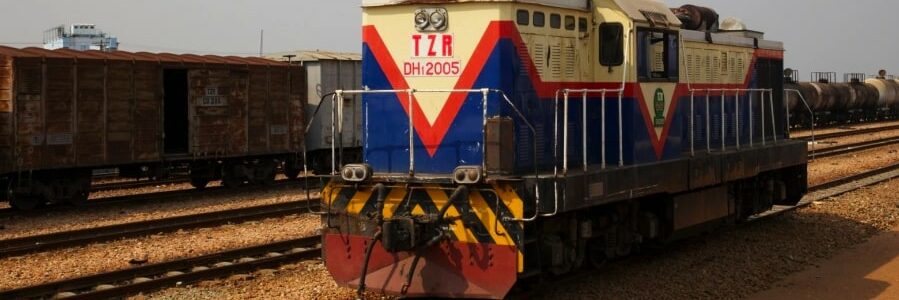
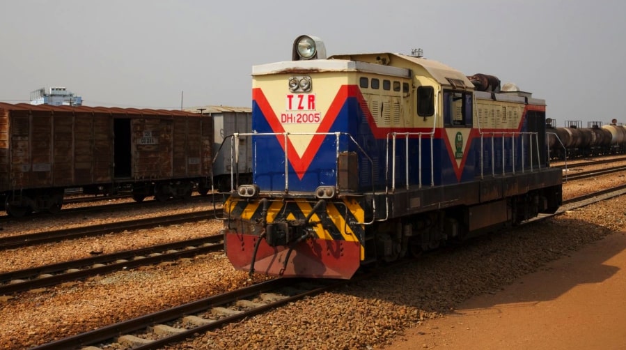
ARCHITECTURAL DESIGN REPORT March 2022 Novel traction systems for sustainable railway futures in LICs HVT/038 This research was funded by UKAID through the UK Foreign, Commonwealth & Development Office under the High Volume Transport Applied Research Programme, managed by IMC Worldwide. The views expressed in this [leaflet/paper/report/other] do not necessarily reflect the UK government’s official policies. Reference No. HVT/038 Lead Organisation/ Consultant University of Birmingham Partner Organisation(s)/ Consultant(s) Title Novel traction systems for sustainable railway futures in LICs Type of document Project Report Theme Low carbon transport Sub-theme Climate Change: Adaptation and Mitigation Author(s) Clive Roberts Stuart Hillmansen Marcelo Blumenfeld Lead contact Clive Roberts (c.roberts.20@bham.ac.uk) Geographical Location(s) Sub-Saharan Africa Abstract This report builds on the capability analysis and the simulation report to further investigate the feasibility of using alternative traction systems to achieve the necessary power. This is done using three of the four case studies previously selected. Further work will assess the costs and benefits of different architectures to explore a physical model and retrofitting plans. Keywords Funding Acknowledgements Issue Status Author(s) Reviewed By Approved By Issue Date 1 Draft Tajud Din Marcelo Blumenfeld 23/02/2022 2 Revision Tajud Din Marcelo Blumenfeld 14/03/2022 3 Revision Tajud Din Marcelo Blumenfeld 25/03/2022 4 Revision Tajud Din Marcelo Blumenfeld 30/03/2022 5 Revision Tajud Din Marcelo Blumenfeld 03/05/2022 i CONTENTS Executive Summary ii Section 1: Introduction 5 1. The overall research challenge 5 2. Aims and objectives of the report 5 3. Relationship with the wider project 5 4. Findings from previous reports 6 Section 2: Case Study 1: Commuter Line (Kampala-Namanve) 7 1. Introduction 7 2. Volumetric Analysis 8 3. Conclusion 10 Section 3: Case study 2: Long distance mixed traffic (Dar es Salaam – Kigoma) 11 1. Introduction 11 2. Volumetric analysis 11 3. Conclusion 14 Section 4: Case Study 3: Medium distance passenger line (Abuja – Kaduna) 15 1. Introduction 15 2. Volumetric analysis 15 3. Conclusion 18 Section 5: Conclusions and next steps 19 ii TABLES Table 1. Case studies examined in the capability analysis report 6 Table 2. Typical characteristics of Diesel Electric ULR Express vehicle 8 Table 3. Components proposed to be removed from ULR 9 Table 4. Components proposed to be added to the hybrid locomotive 10 Table 5. Weight and volume analysis for a hydrogen hybrid ULR 10 Table 6. Typical characteristics of Diesel Electric Locomotive EMD GT22C-3M 12 Table 7. Components proposed to be removed from diesel locomotive 12 Table 8. Components proposed to be added to a hybrid locomotive 13 Table 9. Weight and volume analysis of a hybrid locomotive to provide similar capabilities 13 Table 10. Typical characteristics of a diesel locomotive GE U26C 16 Table 11. Components related to the diesel traction system 16 Table 12. Components related to the hydrogen hybrid traction system 17 Table 13. Weight and volume comparison of diesel and hydrogen hybrid systems 17 Table 14. Summary of volumetric analysis for alternative traction systems in each case study 19 FIGURES Figure 1. Illustration of report within wider logic of the project 5 Figure 2. Exterior of ULR express vehicle 8 Figure 3. External view of an EMD GT22C-3M locomotive 12 Figure 4. GE U26C hauling a freight train in Kenya 16 iii ABBREVIATIONS/ACRONYMS CO2 Carbon Dioxide DEMU Diesel Electric Multiple Unit HVT High Volume Transport IGBT Insulated-gate bipolar transistor kg Kilogram kW Kilowatt kWh Kilowatt Hours LIC Low-income countries OEM Original Equipment Manufacturer SSA Sub-Saharan Africa ULR Ultra-Light Rail iv EXECUTIVE SUMMARY The research project explores cost-effective traction solutions for sustainable railway futures in Sub-Saharan low-income countries. Previous activities have identified four representative case studies, namely in Uganda, Tanzania, Nigeria, and Liberia. These case studies, showcasing different railway service types (commuter, mixed traffic, passenger intercity, heavy haul freight), were simulated using a bespoke tool created for the project. Those were presented in the Capability Analysis report. Once the capabilities were identified, the Simulation Report explored the potential power that alternative traction systems could provide in existing fleets. This report conducts volumetric analyses for three case studies from the project. It was concluded that heavy haul freight is currently beyond the capabilities of non-electrified zero-emissions technologies, therefore the line between Buchanan and Tokadeh in Liberia was not taken forward. Long distance mixed traffic, mediumdistance passenger, and a short-distance commuter line were analysed. Each case study was analysed separately, in a process that estimated the weight and volume changes if the system used for the respective capability was changed to a zero emission one. With that, the process was the same for all case studies. The weight and volume of a “control†existing system (diesel) was calculated, followed by an estimation of the weight and volume of a zero-emission alternative (battery and/or hydrogen hybrid). Both were compared to understand the feasibility of alternative traction systems to deliver equivalent power in equivalent duty cycles. Results indicate that under same conditions, only the commuter line with an ultra-light rail (ULR) vehicle configuration would be ready to fulfil the capabilities without any additional consideration. For the other two case studies, weight was not much of an issue but the volume required to store hydrogen tanks was much greater than those required for diesel (around 40% more). Therefore, it is understood that the study on the use of alternative traction systems for the case studies will also build on an analysis of operations and duty cycles. These will be evaluated in the following steps of retrofitting feasibility, where the appropriate concept of operations will be developed so that traction systems can fit within the existing volumetric characteristics of railway fleet. Such endeavour stands on the technical need to maintain a certain volumetric characteristic of trains to fit existing and/or future gauge envelopes. From there, the feasibility report aims to expand its view towards a technical and economic evaluation of the transition to alternative traction systems. 5 SECTION 1: INTRODUCTION 1. The overall research challenge This applied research project investigates the potential of introducing low (or potentially zero) carbon rail traction systems to Low-income countries (LICs) in Sub-Saharan Africa (SSA). It builds on a capability approach that started with a comprehensive assessment of the railway networks in the region and their respective traffic volumes, to select representative case studies. Those are taken as a means to explore the feasibility of implementing new fleets and/or retrofitting existing fleets with alternative traction systems. In the context of this project, alternative traction systems are those that part away from fuel technologies that are already in the market. Of those, battery electric and hydrogen hybrid systems stand out as emerging solutions and have been explored in further detail. Moreover, the project looks at additional aspects beyond the capability of the traction system within the vehicle domain. It has taken into consideration factors such as the share of renewables in the national grid, and will also explore alternative operational concepts for selected services so that new solutions could potentially be implemented. 2. Aims and objectives of the report This report, titled Architectural Design Report, advances the previous work of capability analyses and simulation of duty cycles to investigate the physical viability of novel traction systems. More specifically, aim of the architectural design report is to conduct volumetric analysis on the traction requirements identified in the capability analysis report, with additional information provided from the simulation reports. The main objectives of the report are to calculate the weight and volume of zero emission traction systems and compare with the existing diesel counterparts. This was done with listing the components involved in each system that are necessary for its safe and effective operation. The task was conducted for three of the four case studies, and each was evaluated and discussed separately. The reason for not including the heavy haul is given in the findings from previous reports. 3. Relationship with the wider project This report sits between capability and retrofitting evaluation in the project, working at a greater level of detail from the case studies selected. It follows from the Simulation Report, which looked at the power requirements of locomotives currently used in the region, to assess whether novel traction systems could deliver similar tractive power. This document relates directly to the capability analysis, where case studies were simulated to find the necessary power and energy requirements of alternative traction systems. The results of this report will feed directly into the retrofitting analysis, where we will investigate the feasibility of converting existing locomotives to zero emission systems. Figure 1. Illustration of report within wider logic of the project 6 4. Findings from previous reports In the Capability Analysis report, several different types of routes were examined. These were as described in Table 1, building on the Capability Analysis report. The Simulation Report was conducted in parallel to identify existing locomotives that could match, or provide similar capabilities, to the requirements from the Capability Analysis. These locomotives from the Simulation Report have been taken forward to the volumetric analysis of novel traction systems. Table 1. Case studies examined in the capability analysis report Route Type of Route / Service Kampala – Namanve Short distance, commuter passenger Dar es Salaam – Kigoma Long distance mixed traffic Buchanan – Tokadeh Medium distance, heavy haul freight Abuja - Kaduna Medium distance passenger These services were simulated in order to determine the tractive requirements. On these grounds, the following decisions have been made going forward: • For a short commuter line between Kampala and Namanve, it seems possible to replace the existing locomotive-hauled rolling stock with lightweight, ultra-light rail vehicles. These reduce the energy requirements and therefore make decarbonisation easier. • For the other case studies of long-distance mixed traffic (Dar es Salaam – Kigoma) and medium distance passenger (Abuja – Kaduna), the energy requirements are somewhat more achievable. These can be achieved by several locomotives in use across the continent, with co-co wheel arrangements and power of around 1500-2000 kW. Both scenarios were simulated in the capability analysis report. • The heavy haul freight train between Buchanan – Tokadeh is unlikely to be the first target for decarbonisation as a ‘low-hanging fruit’. This is because the fuel use for this option is enormous at a potential 1941 kg of hydrogen per round trip. This is far beyond the current state of the art, where current systems are designed with approximately 200kg of hydrogen (such as the Alstom Coradia iLint and the PESA SM42Dn locomotive). There was also no benefit over the round trip to hybridisation of diesel locomotives. Full electrification may be economically justifiable at such tonnage and respective volumes. Therefore, no attempt will be made to analyse a heavy haul freight locomotive for this specific route in this report. • The shunting locomotive identified in the Simulation Report was not taken forward. This is because of the relative rarity of such locomotives and the trend towards less shunting or shunting being performed with the train engine. 7 SECTION 2: CASE STUDY 1: COMMUTER LINE (KAMPALA-NAMANVE) 1. Introduction Kampala to Namanve is a 12 km route located in the suburbs of the Ugandan capital Kampala. The complete track is designed with a 1000 mm narrow gauge. The route is consisting of five stations including the terminus at the Namanve. The track comes with a mild elevation of a few meters for moderate positions. The track serves approximately 2,000 passengers daily over 2 round trips per day. Due to a lack of data, the line speed of this route was assumed to be 40 kph in the capability analysis report. The low speed is considered as a reflection of the current infrastructure, which is not fenced and therefore poses a high risk of collisions with pedestrians and other animals. As it was understood during the period of data collection, most stations on this route do not have suitable platforms or waiting areas. The rolling stock operating on the above-mentioned route is a locomotive-hauled train with an average of 5 coaches which includes only seated coaches. Data was very sparse for that specific fleet. Thus, we decided to approach the capability using a current solution, namely an ultra-lightweight rail vehicle (ULR). The ULR, although unavailable in LICs, was chosen to expand the research on novel traction systems to those where electric traction may be sufficient. In addition, it provides an alternative perspective to retrofitting fleets which are taken more closely in the other two case studies. The ULR considered as an illustrative example in this report is manufactured in the UK by Severn Lamb and is already a hybrid diesel train, therefore also requiring an investigation on the feasibility of converting it to a zero-carbon solution. In the simulation report, the ULR was simulated in a configuration with 5 carriages to match that operating in Uganda. Alternative operations that could require shorter trains were not calculated as they are outside the scope of the project. Based on the results from the capability analysis report, the train that was simulated over the above-mentioned route was assumed to be a set of 5 carriages, with a total mass of 160 tonnes. The simulated train comes with a total power of 840 kW providing 50 kW for auxiliaries and 790 kW for traction. Simulation suggests that with an average speed of 40 km/h the train took 45 minutes to complete one round trip. Results from capability analysis indicate that a total of 304.7 litres of diesel fuel is required to complete a round trip between Kampala and Namanve by a diesel-only configuration. The fuel requirements include the +20% for eventualities. On comparative analysis, the results also indicate that only 7 kg of hydrogen is required to complete a round trip from Kampala to Namanve for a hydrogen hybrid version and 267.06 litres for a diesel hybrid version. The train was also simulated with a battery-only configuration and it is observed that only 183 kWh of energy would be required to complete one round trip from Kampala to Namanve. The capability analysis report indicates that for the above-mentioned route diesel-only ULR produced 1,633 kg of carbon dioxide while the hydrogen hybrid version produced 192 kg (when not using green hydrogen) and the diesel hybrid version produced 1,431 kg of CO2 emissions. The battery only ULR produced zero carbon emission at the point of use. Given the amount of CO2 emissions produced during the journey, a battery-only ULR is the only environmentally friendly option. However, as a second option, a hydrogen hybrid locomotive produced 88% fewer carbon emissions compared to diesel-only ULR, even if not using green hydrogen. The hydrogen hybrid ULR would require considerable hydrogen storage space, specifically, if the operator does not choose to refuel tanks frequently on stops are at terminus station. However, in this case study, the route is quite short and only 2 round trips are carried out during a day. Therefore, a total of 14 kg of hydrogen storage will be considered for conducting volumetric analysis for ULR. Considering the specific energy and energy density of diesel and hydrogen fuel, 1 kg of hydrogen provides 33.3 kWh energy however, 1 litres of diesel fuel provides 10.96 kWh energy. To match the amount of kWh energy required for completion of a round trip for the above-mentioned route 14 kg of hydrogen is required to be stored in hydrogen tanks. 8 2. Volumetric Analysis The Capability Analysis Report identified Severn Lamb’s Ultra Light Rail (ULR) platform as a lightweight design, thus reducing the amount of energy and power needed to complete duty cycles (Figure 2). Below, Table 2 provides the typical characteristics of the vehicle considered. Figure 2. Exterior of ULR express vehicle Table 2. Typical characteristics of Diesel Electric ULR Express vehicle Parameters Characteristics Vehicle Type Diesel Electric light Rail Vehicle Locomotive Weight 160 Tonne Gross Power 840 kW Fuel Capacity 1000 Litres Table 3 presents the weight and volume of the components that would be removed from Diesel Electric ultralight rail and replaced with proposed hybrid version ULR components. There are certain components used during the modelling of OEM trains and proposed hydrogen hybrid train whose volume information was not publicly available. Also, volume of these components could not be assumed due to the nature of their bespoke design and subject to manufacturer installation. However, it is understood that the volume of these components is small compared to main components such as, diesel engine, fuel cells, traction motors, traction batteries and hydrogen tanks etc and they can easily be accommodated within the gaps between the main components, therefore, the volume for such components is assumed zero. 9 Table 3. Components proposed to be removed from ULR Components Weight (kg) Volume (m3 ) Fuel Tank (Dry) 490 1.4 Sand Tank (Empty) 0 0 Engine Battery Box 230 0.017 Auxiliary Battery Box 230 0.017 Auxiliary Heating & Ventilation Unit 164 1.4 Alternator / Generator 2000 1.5 Engine (wet) (x2) 4872 5.4 Turbo Charger 0 0 Traction Motor (x4) 3000 5 Silencer & exhaust pipes 172 0 Charged air cooler (nested pipework) 100 0 Lube Oil 627 0 Cooling Water Tank (Dry) 400 1.25 Miscellaneous/Others 1000 2 Total 13,303 kg 18 m3 Table 4 presents the weight, quantity, and volume of the components that are required to be considered during modelling of the proposed hydrogen hybrid train. Installation of onboard hydrogen gas and tanks is based on the kWh energy available on OEM diesel-electric version. After applying 30% efficiency of a diesel engine, 10,960 kWh energy was available for traction at wheels. However, the results from simulation reports indicate that it only requires 14 kg of hydrogen for 2 round trips, therefore only 1 carbon fibre tank is enough to be modelled onboard as it contains 27.8 kg of hydrogen which is more than the required quantity. A battery pack of 220 kWh is also modelled for the hydrogen hybrid locomotive along with a stack of seven 100 kW fuel cells to meet the power requirements of 840 kW. Since the ULR is a diesel-electric train and is already equipped with traction motors, therefore the same traction motors will be used in a hybrid version of ULR. 10 Table 4. Components proposed to be added to the hybrid locomotive Components Weight/Item (kg) Quantity Total Weight (kg) Volume (m3 ) Fuel Cell Modules 280 7 1,960 3.5 Fuel Cell Coolants 44 7 308 1.03 Compressor/ Air subsystem 61 7 427 0.7 Hydrogen Pipework, Valves & Ancillaries 100 5 500 0 Hydrogen Tanks 324 1 324 1.91 Hydrogen (H2) 27.8 1 27.8 0 Battery Pack 352 7 2,464 1.75 Traction Motors 600 5 3000 7.2 IGBT Converter 300 5 1,500 0 Total 13,111 kg 16 m3 Table 5 presents the OEM ULR express final weight and volume analysis and its hybrid version. It is observed that the hydrogen hybrid version components do not require additional space to be modelled onboard, subsequently not exceeding the available space on an OEM ULR express. Generally, a large amount of volume is consumed by modelling hydrogen tanks but in this case study, only one hydrogen tank was used in simulated model, which was sufficient to provide the required amount of energy. Table 5. Weight and volume analysis for a hydrogen hybrid ULR Components Weight (kg) Volume (m3 ) OEM Diesel Electric Locomotive 160,000 151 Removed Components 13,303 18 Added Components 10,511 14 Hybrid Locomotive 157,208 147 Change -1.75% -2.65% Conclusion Within Weight Within Volume 3. Conclusion Evaluating the volumetric study carried out for conversion of ultra-light rail (ULR), it is observed that the conversion is feasible for this specific train. The major challenge in the conversion of conventional locomotives/trains is the storage for enough hydrogen fuel to complete the journey. Typically, a volumetric study is conducted based on the availability of the same amount of energy as carried by a conventional locomotive on the given route. However, in this case study the amount of energy required was already known, therefore, an adequate amount of hydrogen storage was modelled onboard the simulated train. Given the space and volume required for the storage of hydrogen fuel, it does not cross the available threshold limit for weight and volume. Apart from that, since it is a very small route and consists of four stations there will be moderate braking on this route which will also regenerate a significant amount of energy. Therefore, it is concluded that the conversion of ULR is feasible for the hybrid hydrogen version as it does not exceed the conversion limits established by volumetric analysis. 11 SECTION 3: CASE STUDY 2: LONG DISTANCE MIXED TRAFFIC (DAR ES SALAAM – KIGOMA) 1. Introduction Dar es Salaam to Kigoma route is a 1,200 km track in Tanzania that starts from Dar es Salaam on the Indian ocean coast towards Kigoma on the shore of Lake Tanganyika. The track was built during 1905 and 1914 starting from Dar es Salaam to Kigoma. The complete track is designed with a 1,000 mm narrow gauge. The track comes with significant elevation gains throughout such as towards Tabora, there is an elevation of 1,300 m, towards Mwanza, there is an elevation of 1,140 m and towards Kigoma, there a depression of 770 m. The rolling stock operating on the above-mentioned route is a locomotive-hauled train with an average of 10 coaches which includes both sleepers and seated coaches. Since the lack of availability of data about a specific train that operates on the mentioned route, an example locomotive EMD GT22C-3M was considered for simulation and architectural design. The locomotive weighs 110 tonnes and comes with a gross power of 1,850 kW. It has a diesel-electric traction system and has a capacity of 7,500 l of diesel fuel. Based on the results from the capability analysis report, the train that was simulated over the abovementioned route was assumed to be a set of 11 carriages, with a total mass of 597.5 tonnes. The simulated train comes with a total power of 2,000 kW providing 200 kW for auxiliaries and 1,800 kW for traction. Since the route from Dar es Salaam to Kigoma is very long, it was divided into three sections to perform simulations efficiently. The sections were (Dar es Salaam - Mahundi Jn, Mahundi Jn - Tabora, Tabora - Kigoma). Simulation suggests that with an average speed of 39 km/h the train takes 21.5 hours from Dar es Salaam to Tabora and further 10.5 Hours to Kigoma. Results from capability analysis indicate that a total of 12,394 l of diesel fuel is required to complete a round trip from Dar es Salaam to Kigoma using a diesel-only locomotive. The fuel requirements include the +20% for eventualities. On comparative analysis, the results also indicate that only 1,498 kg of hydrogen would be required to complete a round trip from Dar es Salaam to Kigoma for a hydrogen hybrid version and 12,719 l for a diesel hybrid version. The capability analysis report indicates that for the above-mentioned route diesel locomotive train produced 33,214 kg of carbon dioxide while the hydrogen hybrid version produced 20,508 kg and the diesel hybrid version produced 34,084 kg of CO2 emissions. Given the amount of CO2 emissions produced during the journey, a hydrogen hybrid locomotive is the only environmentally friendly option that produces 38% fewer carbon emissions. The hydrogen hybrid locomotive requires considerable hydrogen storage, specifically, if the operator does not choose to refuel tanks frequently on stops are at terminus station. Considering the specific energy and energy density of diesel and hydrogen fuel, 1 kg of hydrogen provides 33.3 kWh energy however, 1 l of diesel fuel provides 10.96 kWh energy. To match the amount of kWh energy required for completion of a round trip for the above-mentioned route 1498 kg of hydrogen is required to be stored in hydrogen tanks. Let alone these empty hydrogen tanks will greatly affect the overall mass of the locomotive and will be presented in dept in the next section. 2. Volumetric analysis To determine the requirements for a decarbonised freight locomotive for Sub-Saharan Africa, first, a search for existing locomotives of suitable size was undertaken. An example locomotive is the EMD GT22C-3M (Figure 3). This locomotive has been chosen as an example of a freight locomotive with a maximum power output that is conceivably achievable with the present state of the art of novel traction technologies. Table 6 shows the original equipment manufacturer (OEM) characteristics of Locomotive EMD GT22C-3M used in the previous simulation study. 12 Figure 3. External view of an EMD GT22C-3M locomotive Table 6. Typical characteristics of Diesel Electric Locomotive EMD GT22C-3M Parameters Characteristics Vehicle Type Diesel Electric Locomotive Locomotive Weight 110 Tonne Gross Power 1847 kW Fuel Capacity 6700 Litres Table 7 presents the weight and volume of the components that shall be removed from Diesel Electric Locomotive EMD GT22C-3M and replaced with proposed hybrid version locomotive components. Table 7. Components proposed to be removed from diesel locomotive Components Weight (kg) Volume (m3 ) Fuel Tank (Dry) 2345 6.7 Sand Tank (Empty) 238 0.68 Engine Battery Box 230 0.017 Auxiliary Battery Box 230 0.017 Auxiliary Heating & Ventilation Unit 100 1.4 Alternator / Generator (AR10) 2000 1.5 Engine EMD 12-645E3C (wet) 12800 5.4 Turbo Charger 560 1.2 Traction Motor EMD D31 (x6) 10800 14.4 Silencer & exhaust pipes 172 0 Charged air cooler (nested pipework) 100 0 Lube Oil 627 0 Cooling Water Tank (Dry) 787 2.25 Miscellaneous/Others 1000 2 Total 32,024.5 kg 35.5 m3 13 Table 8 presents the weight, quantity, and volume of the components that are required to be modelled for the proposed hydrogen hybrid locomotive. Assessment of modelling onboard hydrogen gas and tanks is based on the kWh energy available on OEM diesel-electric version. After applying 30% efficiency of a diesel engine, 22,029 kWh energy was available for traction at wheels. Considering this, 1,102 kg hydrogen gas is stored in 40 carbon fibre tanks, which will provide approximately 22,029 kWh energy. A battery pack of 391 kWh is also modelled onboard a hydrogen hybrid locomotive along with a stack of fifteen 100 kW fuel cells to meet the power requirements of 1,847 kW. Since the EMD GT22C-3M is a diesel-electric locomotive and is already equipped with 6 traction motors, therefore the same traction motors will be used in a hybrid locomotive. Table 8. Components proposed to be added to a hybrid locomotive Components Weight/Item (kg) Quantity Total Weight (kg) Volume (m3 ) Fuel Cell Modules 280 15 4200 7.5 Fuel Cell Coolants 44 15 660 2.21 Compressor/ Air subsystem 61 15 915 1.5 Hydrogen Pipework, Valves & Ancillaries 100 8 800 0 Hydrogen Tanks 324 40 12,960 76.4 Hydrogen (H2) 27.8 40 1,122 0 Battery Pack 352 13 4576 3.25 Traction Motors 1800 6 10800 14.4 IGBT Converter 300 6 1800 0 Total 37,833 kg 105 m3 Table 9 presents the OEM diesel-electric locomotive's final weight and volume analysis and its hybrid locomotive version. It is observed that the hybrid locomotive components required additional space to be modelled onboard, which exceeds the available space on a diesel locomotive. A large amount of volume is consumed by using 40 hydrogen tanks in simulated hydrogen hybrid train covering 76.4 m3 space. Also, the hybrid locomotive version exceeds the OEM locomotive weight threshold. Table 9. Weight and volume analysis of a hybrid locomotive to provide similar capabilities Components Weight (kg) Volume (m3 ) OEM Diesel Electric Locomotive 110,000 184 Removed Components 32,024.5 35.5 Added Components 37,833 105 Hybrid Locomotive 115,808.5 253.5 Change +5.3% +37.7% Conclusion Over-weight Over-volume 14 3. Conclusion Evaluating the volumetric study carried based on a diesel-electric locomotive EMD GT22C-3M, it is observed that a hydrogen hybrid system would require a much greater volume to fulfil the capability requirements of the long distance line between Dar es Salaam and Kigoma. The major challenge is the storage for enough hydrogen fuel to complete the 1,200km journey. The above volumetric study is conducted with regards to the availability of the same amount of energy as carried by a conventional locomotive on the given route in this case study. To match the available energy for traction and auxiliaries a fraction of hydrogen is required but to store that hydrogen, enormous storage is required. Given the space and volume required for the storage of hydrogen fuel, it crosses the available threshold limit for weight and volume. Apart from that, since it’s a very long route and with minimum braking, the amount of regenerative energy is negligible. To recharge, the battery pack present onboard the hydrogen hybrid locomotive an excess amount of hydrogen will be used. That excessive amount will require additional space and weight for installation onboard locomotive which already does not have enough space for basic installation. Therefore, considering only the requirements for a round-trip without refuelling in between, it is concluded that it is unlikely that a hybrid hydrogen version would be feasible from a volumetric perspective. 15 SECTION 4: CASE STUDY 3: MEDIUM DISTANCE PASSENGER LINE (ABUJA – KADUNA) 1. Introduction The route Abuja-Kaduna is located in Nigeria. It is 185 km long and runs from the Nigerian capital Abuja to the city of Kaduna. The track was built by China Civil and Engineering Construction company between 2011-2014. This track is among the first modern standard gauge line in Nigeria. Currently, all passenger trains on this route are cruising at a maximum speed of 100 kph consuming 2 hours journey time for both sides. The track comes with a moderate elevation at a few locations as on the way back from Kaduna to Abuja there are 2 major elevation points. The first elevation section lasts for approximately 60 km and the second lasts for 30 km. Alternatively, this elevation will be considered as depression while traveling from Abuja towards Kaduna. The rolling stock operating on the above-mentioned route is a locomotive-hauled train with an average of 6 coaches which includes seated coaches only. Since the lack of availability of data about a specific train that operates on the mentioned route, an example locomotive GE U26 is considered for simulation and architectural design. The locomotive weighs 100 tonnes and comes with a gross power of 1,500 kW. It has a diesel-electric traction system and has a capacity of 7,500 l of diesel fuel. Based on the results from the capability analysis report, the train that was simulated over the abovementioned route was assumed to be a set of 7 carriages, with a total mass of 340 tonnes. The simulated train comes with a total power of 1,500 kW providing 120 kW for auxiliaries and 1,380 kW for traction. Simulation suggests that with an average speed of 100 km/h the train took 4 hours for a return trip from Abuja to Kaduna. Results from capability analysis indicate that a total of 1,358.43 l of diesel fuel is required to complete a round trip from Abuja to Kaduna by a diesel-only locomotive. The fuel requirements include the +20% for eventualities and fuel required for charging the batteries. On comparative analysis, the results also indicate that only 172.08 kg of hydrogen is required to complete a round trip from Abuja to Kaduna for a hydrogen hybrid version and 1,363.85 l for a diesel hybrid version. The capability analysis report indicates that for the above-mentioned route diesel locomotive train produced 7,282 kg of carbon dioxide while the hydrogen hybrid version produced 4,715 kg and the diesel hybrid version produced 7,311 kg of CO2 emissions. Given the amount of CO2 emissions produced during the journey, a hydrogen hybrid locomotive is the only environmentally friendly option that produces 35% fewer carbon emissions. As mentioned in previous case studies, the hydrogen hybrid locomotive requires considerable hydrogen storage, specifically, if the operator does not choose to refuel tanks frequently on stops are at terminus station. Considering the specific energy and energy density of diesel and hydrogen fuel, 1 kg of hydrogen provides 33.3 kWh energy however, 1 l of diesel fuel provides 10.96 kWh energy. To match the amount of kWh energy required for completion of a round trip for the above-mentioned route 172.08 kg of hydrogen is required to be stored in hydrogen tanks. Let alone these empty hydrogen tanks will greatly affect the overall mass of the locomotive and will be presented in dept in the next section. 2. Volumetric analysis To determine passenger requirements, a hypothetical train was simulated based upon some real-life data. An example locomotive is the GE U26C (Figure 4), which has the critical characteristics shown in Table 1. This locomotive has been chosen as a benchmark as it is used in passenger service on the African continent and has a power output achievable using the present state of the art of novel traction technologies. 16 Figure 4. GE U26C hauling a freight train in Kenya Table 10. Typical characteristics of a diesel locomotive GE U26C Parameters Characteristics Vehicle Type Diesel Electric Locomotive Locomotive Weight 100 Tonne Gross Power 1500 kW Fuel Capacity 7500 Litres Table 11 presents the weight and volume of the components removed from Diesel Electric Locomotive GE U26C and replaced with proposed hybrid version locomotive components. Table 11. Components related to the diesel traction system Components Weight (kg) Volume (m3 ) Fuel Tank (Dry) 2625 7.5 Sand Tank (Empty) 175 0.5 Engine Battery Box 230 0.017 Auxiliary Battery Box 230 0.017 Auxiliary Heating & Ventilation Unit 100 1.4 Alternator / Generator (GTA11 C.C) 2000 1.5 Engine GE 7FDL-12 (wet) 16215 6.4 Turbo Charger 560 1.2 Traction Motor GE-761A17 (x6) 10380 11.4 Silencer & exhaust pipes 172 0 Charged air cooler (nested pipework) 100 0 Lube Oil 276 0 Cooling Water Tank (Dry) 687 2 Miscellaneous/Others 1000 2 Total 34,784 kg 35.93 m3 17 Table 12Table 12 presents the weight, quantity, and volume of the components that are required to be modelled for the proposed hydrogen hybrid locomotive. Assessment for the modelling of onboard hydrogen gas and tanks is based on the kWh energy available on OEM diesel-electric version. After applying the 30% efficiency of a diesel engine, 24,660 kWh energy was available for traction at wheels. Considering this, 1,234 kg hydrogen gas is stored in 44 carbon fibre tanks, which will provide approximately 22,029 kWh energy. A battery pack of 550 kWh is also modelled for the hydrogen hybrid locomotive along with the stack of fifteen 100 kW fuel cells to meet the power requirements of 2,050 kW. Since the GE U26C is a diesel-electric locomotive and is already equipped with 6 traction motors, therefore same traction motors will be used in the hybrid locomotive. Table 12. Components related to the hydrogen hybrid traction system Components Weight/Item (kg) Quantity Total Weight (kg) Volume (m3 ) Fuel Cell Modules 280 15 4200 7.5 Fuel Cell Coolants 44 15 660 2.21 Compressor/ Air subsystem 61 15 915 1.5 Hydrogen Pipework, Valves & Ancillaries 100 8 800 0 Hydrogen Tanks 324 44 14,256 84.04 Hydrogen (H2) 27.8 44 1,223.2 0 Battery Pack 352 18 6336 4.5 Traction Motors 1730 6 10380 11.4 IGBT Converter 300 6 1800 0 Total 40,570 kg 111 m3 Table 13 presents the final weight and volume analysis of the OEM diesel-electric locomotive and its hybrid locomotive version. It is observed that the hybrid locomotive components required an additional 75.25 cubic meter space to be installed onboard, which exceeds the available space on a diesel locomotive. A large amount of volume is consumed by using 44 hydrogen tanks in simulated model which cover 84.04 m3 space. Also, the hybrid locomotive version exceeds the OEM locomotive weight threshold by 6,23 kg. Table 13. Weight and volume comparison of diesel and hydrogen hybrid systems Components Weight (kg) Volume (m3 ) OEM Diesel Locomotive 100,000 179.55 Removed Components 34,784 33.94 Added Components 40,570 111 Hybrid Locomotive 105,786 256.6 Change +5.78% +42.9% Conclusion Over-weight Over-volume 18 3. Conclusion Evaluating the volumetric study carried out based on a locomotive GE U26C, it is observed that a hydrogen hybrid system would lead to both more weight and more volume requirements than a diesel equivalent. mentioned in previous case studies in this report, the major issue these locomotives will face during retrofitting will be installing the hydrogen tanks. The calculation of hydrogen storage is based on the amount of diesel fuel a conventional locomotive can carry. To match the storage factor, the respective amount of hydrogen tanks should be installed. However, the more hydrogen tanks required for storage, the more locomotive will get overweight. The above volumetric study is conducted with regards to the availability of the same amount of energy as carried by a conventional locomotive on the given route in this case study. Given the space and volume required for the storage of hydrogen fuel, it crosses the available threshold limit for weight and volume. Although this route is considerably shorter than the previous route studied in case study 2, it consists of only three stations. This results in minimum braking; hence, the amount of regenerative energy is also negligible on this route. To recharge, the battery pack present onboard the simulated hydrogen hybrid version an excess amount of hydrogen will be used. That excessive amount will require additional space and weight to be modelled onboard the simulated hybrid locomotive which already does not have enough space for basic installation. Therefore, it is concluded that a system that would cater for the current duty cycles would require a considerably larger volume than diesel ones. It logically follows that such conversion would need a review of the refuelling schedules to enable the use of hydrogen hybrid solutions. 19 SECTION 5: CONCLUSIONS AND NEXT STEPS This report combined findings from the Capability Analysis and the Simulation reports to conduct a systematic volumetric analysis of the alternative traction systems required to match the capabilities of their diesel equivalent. For that, three of the four initial case studies were analysed: 1. Commuter line (Kampala - Namanve) 2. Long-distance mixed traffic (Dar es Salaam – Kigoma) 3. Medium-distance passenger services (Abuja – Kaduna) The fourth case study of the heavy haul line in Liberia (Buchanan – Tokadeh) was not taken forward to this stage because of the power requirements of the line, which are currently beyond the capabilities of any alternative traction. Moreover, the line operates high traffic densities which may justify investments in electrification. For the other case studies, the methodology was straightforward and based on technical specifications gathered in previous reports. For each line, the power requirements (in the form of kWh and/or kg of hydrogen) were derived from the Capability Analysis report. For the volumetric comparison with a diesel counterpart, locomotives were drawn from the Simulation Report. The study compared existing and novel traction from both weight and volume perspectives. It estimated the weight associated with diesel traction systems and equivalent battery/hydrogen hybrid systems, to then compare them for each case study. We concluded that conventional vehicle operating on the shorter commuter route is feasible for conversion based on the energy required for daily trips. Due to the lack of data available, that was based on an illustrative use of modern ultra-light rail (ULR) vehicles in a similar configuration. Results show that a battery-electric system would also suffice for the line, demonstrating a potential feasibility in the use of alternative traction for such cases. The longer passenger and mixed traffic routes, however, showed opposite results. Both long haul freight and passenger locomotives require to store a large amount of hydrogen which subsequently requires installing a large number of hydrogen tanks. This installation will technically increase the overall weight and volume of the train. Both cases did not require much more weight than a diesel equivalent but required a considerably larger volume (around 40% more), which is challenging at this stage. Table 14 below summarises our findings. Table 14. Summary of volumetric analysis for alternative traction systems in each case study Case study Weight (kg) Volume (m3 ) Commuter Line with ULR (Kampala – Namanve) Within Weight (-1.75%) Within Volume (-2.65%) Mixed traffic long-distance (Dar es Salaam – Kigoma) Over-weight (+5.3 %) Over-volume (+37.7%) Medium distance passenger (Abuja – Kaduna) Over-weight (+5.78%) Over-volume (+42.9%) Despite case studies initially suggesting that ULR is a feasible choice as being within weight and volume, the technology is still in the development and full-scale implementation is yet to be carried out by manufacturers. ULR is also not a commercial solution to be integrated for such routes in Saharan countries due to their outdated timetabling and scheduling structure. This would require an entire overhaul of technology and regulatory capabilities. Therefore, ULR may not be deemed a cost-effective solution for the “Kampala-Namanve†route. Considering this it has decided to proceed with the Tanzania case study because it’s more realistic and representative of sub-Saharan railway operations. It must be highlighted that our calculations at this stage have maintained the concept of operations intact, meaning that the requirements were based on the same duty cycles of diesel trains. Therefore, the next steps from this report will develop in two ways toward a more detailed analysis of retrofitting feasibility. Firstly, alternative concepts of operations may be pursued to fit within the volumetric characteristics of current fleets. Then, detailed design of the viable case studies in the form of a more refined model. This will allow a more detailed examination of component choices and should also look at different configurations for the most appropriate solutions in terms of technical viability, operational performance, and capital and operational costs. 20 Birmingham Centre for Railway Research and Education University of Birmingham Edgbaston Birmingham B15 2TT United Kingdom Tel: +44 (0)121 414 2626 Email: m.blumenfeld@bham.ac.uk Web: www.birmingham.ac.uk/research/railway/index.aspx